2011-05-16

Power Steering - slightly technical

I got a gangster deal on my whole Integra setup (Front knuckles, brakes, arms, subframe, steering rack; Rear trailing arms, brakes, control arms, camber links, compensator links; all 4 spring and damper assemblies), so my original intent was to use as much of that as possible to save money.  Turns out lots of the suspension was not ideal for a build that I wanted "done right", so I sold it to a coworker for a decent loss.  I did, however, hang onto the subframe and steering rack.

I knew that the initial build of my car would be without power steering, mostly motivated by these factors:
-cleans up engine bay
-simplicity
-weight
-I was shooting to build a real "driver's car".  May be laughable at its current state, but take a look at the McLaren F1.  That car had no systems to impede your driving experience, such as traction control, ABS, and you guessed it, power steering.  As an additional bonus, my car will cost about $950,000 less than the McLaren F1.  Whatever it takes to rationalize spending lots of money on a 13-year-old stripped-out economy car.

I digress...  my initial plan was to convert the power rack to manual; or more specifically, looping the lines to create a closed system that was unassisted by high-pressure fluid.

I've read many ways to do this on the trusty internet.  In the interest of learning something, I decided to take the steering gear apart and figure out (a) what I was doing, and (b) if this was a good idea.

Enter picture 1, the steering gear disassembled:


Whats going on: 
***Top Left is the steering gear, or the pinion assembly.  The splined portion is what mates to the universal joint (just inside the firewall) and the steering column.
***Top Right is the DC Integra universal joint, which I heard is required to mount this rack to an EK chassis
***Bottom: the steering gear housing with I/O ports to the pump, reservoir, and either side of the rack pistion.

Looking more closely at the steering gear, there's a cage with 3 oiling grooves and 4 black seals.  Take a look at those inner grooves


Next take a look at the pinion shaft assembly without that cage:


Similar looking grooves... try to figure out what's going on.  Check out the Helm manual (Factory service manual) for a phenomenal description of the power steering system, or look it up on howstuffworks or something.

It's hard to see, but there's a small diameter torsion bar inside the inner cage (or wtf that thing's called...)

The next pic gives you an idea of how the fluid's distributed:


--The left-most holes (to the left of the outer cage) are the low-pressure return to the reservoir.  
--The left-most groove is the high-pressure feed to one side of the power piston.
--The Center groove is the high-pressure feed from the pump
--The right-most groove is the high-press feed to the other side of the power piston.

You also see my handiwork in the background... super destructive removal of the circlip holding the outer cage to the pinion shaft assembly.  Once I replace that, the rack is again functional.

Super-summarized Conclusion: After all this, I've decided that converting this rack to manual steering (no fluid assist) would be using the steering gear structure and valving-system outside of its design intent.  I'm all for modifying stuff, but being "outside the design intent" for a relatively important system like Steering may not be the best idea.

There aren't pictures like this anywhere else on the internet (afaik), so hopefully you can learn something here.

The next task is to try and locate a proper manual steering rack.

To Pick-and-Pull... and beyond...
-Jkwan


Removing the rack and RR Eng Mount Bolt

Pretty quick post with some pictures.

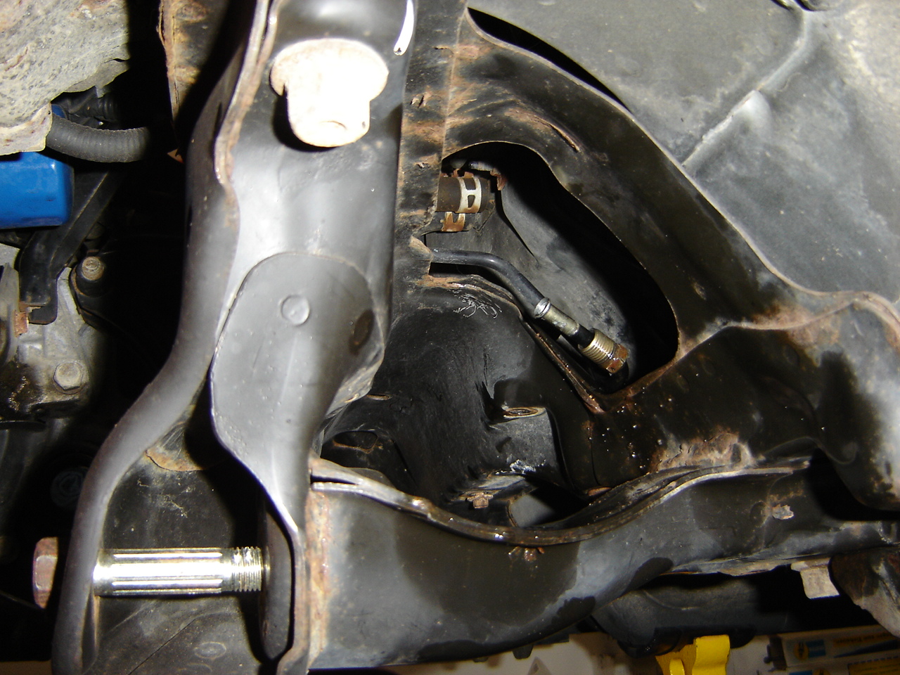
Removing the steering rack may be one of the most annoying things I've done on this car.  First, the tool clearance to remove the feed and return fittings is absolutely horrid.  Once you do get that done, snaking the rack out of the subframe is quite the puzzle.  But it can be done before the subframe comes off.  Here's the aftermath


Now time to remove the rear engine mount bolt.  As I will learn, this is very easy on an EG or DC from underneath the car, but this isn't the case on an EK.  Time to get the extensions and a universal joint out.


Those pics show the easiest way to do this.  Grab roughly 3 feet of 1/2" drive extensions (I hate to keep plugging Sears, but they have a really useful extension for ~$30) and remove the bolt from outside the car.

Now a moment of zen


kay thanks bye
-jkwan

2011-05-15

How to drain the Power Steering Fluid

Before you do this job, go to the auto parts store and the hardware store because you'll need some things.  Get :
1 foot of 3/8" ID power steering hose ($2)
5 feet of 5/16" ID, 7/16" OD Vinyl Tubing ($1.50)
1qty, #4 Hose clamp (worm clamp) ($2 for 2-pack)
1qty, 3/8-24x1" hex cap screw ($4 for 2-pack)
2qty, gatorade, any flavor (20 oz or up)

How to do it:
(1) drink one gatorade and rinse the bottle out.  Drill two holes (one 3/8" hole, one smaller, any size).  The 3/8" hole is for a hose, the other is a breather.


(2) Construct this glorified plug using the above parts and your brain.


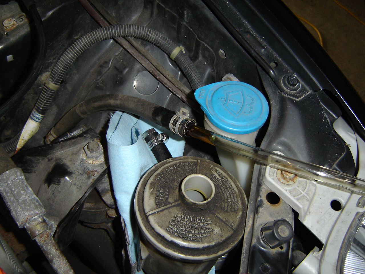
Here's a pic of your PS reservoir for reference.  The hose on the right is the RETURN from the rack.  The hose off to the left (clips into the reservoir) is the FEED side into the pump.  You may have just learned something.


(3) Create this super setup.  Slip the plug onto the Return nipple (what would you call it?) and simultaneously slip the clear tubing INTO the return hose.  Shove it right in there, it will fit.  Put the hose clamp back on there to prevent the tubing from slipping out.  It's also a great idea to (a) put a shop towel down there to keep PS fluid off your car body, and (b) take the red cap off the reservoir at this point to open up the system.


(4) Shove the other end of the clear plastic tubing into the hole in your gatorade bottle.

(5) Turn the wheel side-to-side to pump the fluid out.  You will have to turn the wheel many times.  Your friends will walk into the garage and wonder what's wrong with you, but keep pumping the fluid out.  When you're done, you'll have about this much PS fluid.  It won't be ALL the fluid in the system (the rest will drain onto your face as you remove the rack), but it will at least be most of the fluid.


(6) Drink the other gatorade.

Now it's time to call it a day because that was such a difficult job.

laterz
-Jkwan

Front Suspension

I've been working super slowly on this car, and I've been updating my online Civic build diary even less.  Anyways, I'm at a slightly more advanced state of progress, but I will retroactively update to show what's going into this project.

Here's a couple pics of the front suspension parts that came off.  One of the biggest challenges with working on a car of this age is rust, especially when we're talking about the little cotter pins that go through all the ball joint castle nuts.  TIP: soak the pins and nuts in PB Blaster and let sit for 10ish minutes.  Then straighten the pins as much as you can, clamp vice-grips on the open end of the pins roughly 2mm from the castle nut.  Tap with a hammer and repeat until you can "easily" pull the pin out by using a Craftsman cotter pin puller (an 8 dollar tool that will save you lots of frustration).  Once all 6 cotter pins are out (both steering rod ends, upper arm ball joints, and lower ball joints), removing the nuts and the rest of the suspension is pretty easy, assuming you have ball-joint separators (either a fork or a powerscrew type).  If you don't, you can just neanderthal it and whack it with a BFH (Big something Hammer.  Nobody quite knows what the F stands for).


Here's what you have left: Subframe (you can also correctly call it a cross-member since Pick and Pull charges less money for it that way...) bolted to the unibody, steering rack mounted up there with the rod ends just hangin out, and your car magically suspended in midair.

NOTE: I had jackstands placed here for awhile since it looked structural.  I noticed no ill-effects from supporting the car here.  However, this is not the factory-service-manual recommended jack location, so place stands here at your own risk.


After taking the front suspension apart, I noticed something pretty interesting.  I placed 94 Integra RS arms on top of my 98 Civic DX arms, and they looked basically identical (at least in the mounting dimensions).  To the best of my tape-measuring abilities, the spindle, shock, and subframe mounting locations are spot-on between the two.  It seems like the main difference is that the Integra arms have a swaybar mounting hole.  This will be important to me and as such, I will use the Integra front suspension arms.  I do need to put some new bushings in though.


The next pic shows the rack and subframe.  These need to come out obviously.  Before you can do that, you need to take the shifter linkages off the gearbox.  The stabilizer arm (red poly bushing) is easy to take off... the other one... not so much.  I used a small hex bit, and extension, and my 4lb Kobalt hammer, and the roll pin came out.  But it certainly is a PITA.  (disclaimer... some people swear against using a hammer here so use one at your own risk).


And here's a picture of my rack.  Oh car humor, I crack myself up.  This is a power steering rack from an Integra.  In the future I will realize this is not the rack for me, but for now, we can pretend I will use this one with my Integra subframe.


Here's all my crap stored behind and under my Civic.  I need to get rid of this.


Till next time
buhbye
-jkwan

2011-03-07

actual progress !

Taking the rear suspension off...  Picture heavy:

A couple things to note: 
start with the compensator link and remove bolt holding it to the body (this is the adjustable bolt).  Then, support the rear trailing arms with a floor jack and a 2x4 (placed under the large bushing) and remove the bolts.  This is because the bolts do hold some weight, and you want to avoid damaging the last few threads as you remove the bolts.  Remove the RR Lower subframe to trailing arm bolt.  Finally, support the lower control arm between the shock fork and the trailing arm, remove the camber link bolts, and remove the shock bolts in the trunk.  Have a friend help you.  Or pay a stranger in beer to help you.  your call.


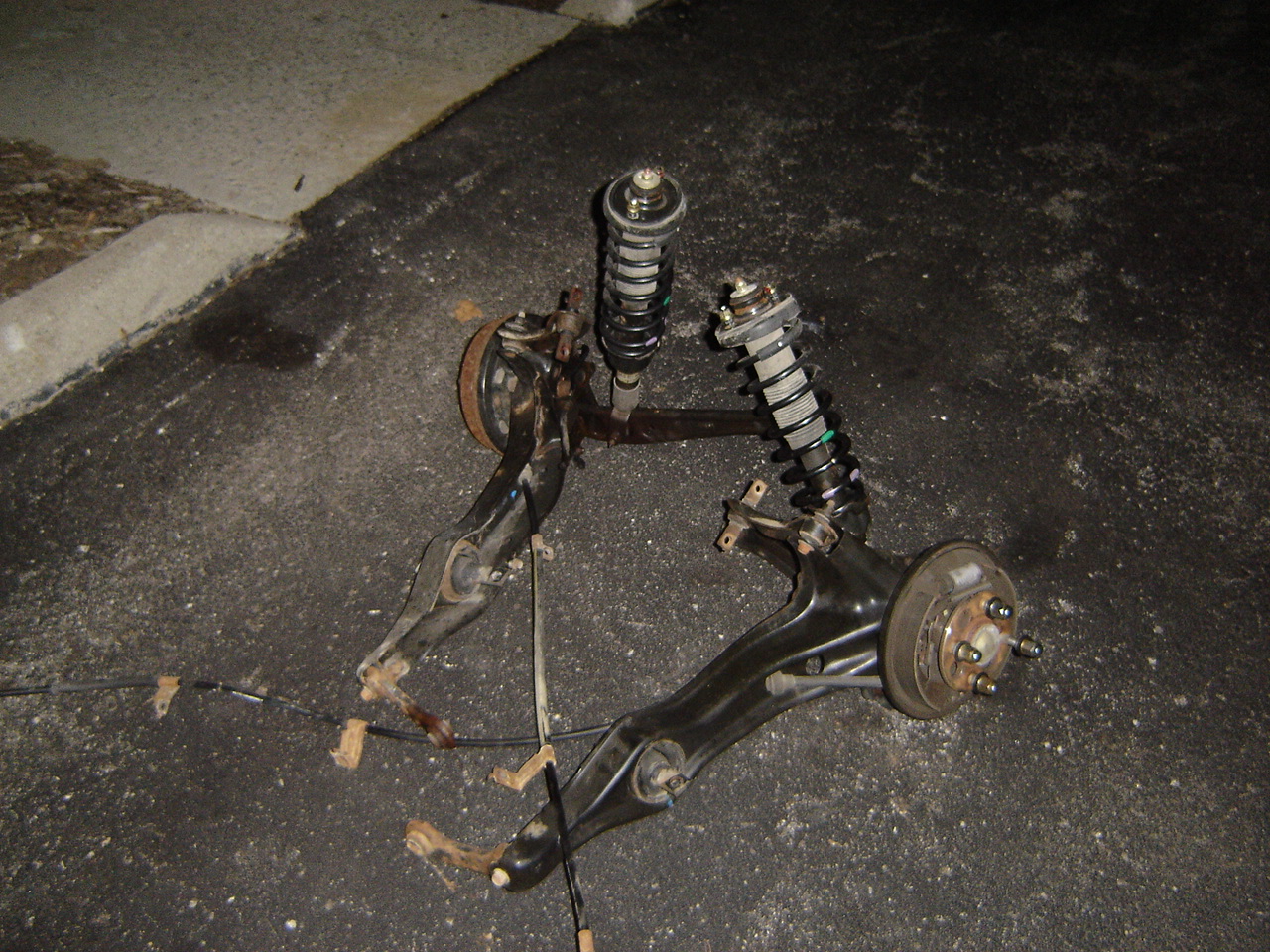
Now what! No left RR sus remaining!  And as if by magic, the right side is gone too.  Super Efficiency.


Nice paperweights, eh?

aaand thanks to my homeslice Taku for the help with the rear suspension.  smile for the camera Taku.


Walk to the nearest pub to celebrate.

bye
-jkwan

pic heavy post with little content...

...so far I've been working at a pace that can be best described as "leisurely".  I also don't update this blog much.  Regardless, please enjoy some pics!

So here's my car just chillin, as well as a sweet nightshot of the workshop.  Invest in some cheap Home Depot shop lights and you won't be disappointed.


As I mentioned before, now's a fantastic time to take off the B-pipe.  Use a couple drops of this (RC car silicone shock oil, any weight will do) on the steel exhaust hangers, and the rubber grommets will pop right off.


and there's your b-pipe


the next step is to take the rear suspension off.  The rear suspension is pretty heavy.  Not like hundreds of pounds, but heavy enough where you want to lift it using your knees to avoid killing your back.  An important consideration is that you will be removing that weight from the back of a car that's on jackstands, and while I don't think the car is going to go catapulting forward when the RR sus is removed, it's a good idea to toss some weight in the trunk to make sure everything stays planted.  Tires are a smart choice.  Word to the wise, this also frees up garage space.


Finally, make sure you have some choice music before you proceed to the next step.


till next time
-jkwan

2011-02-13

E-Brake cables

Last night after dinner and a frothy beverage or two, I decided to make some progress on the hatchback.

To take the rear sus out as a unit, I still needed to disconnect the e-brake cables and drain and disconnect the hydraulic lines.  We tried to take the cables off at the drum, but it looked more difficult than taking them out through the cabin.  So enjoy a picture of the drum brakes as they are headed to the scrapheap.


The rear portion of my center console was held in with two screws, but I feel like there should have been more.  Anyways, keep undoing hardware until you get it here


Underneath, undo the brackets and pass the cables through the center tunnel rubbers.


I left the exhaust B-pipe attached and just unbolted and pushed around the heatshield, but to put cables back in, I will need to remove the B-pipe.  So if you're doing this, just take the B-pipe out now and make it a bunch easier.

I also noticed that at some point in this vehicle's illustrious history, the weld nut broke off and some resourceful individual replaced it with a standard flange nut.  By the way, that is the rear hole as seen from inside the cabin.


So now the cables look like this, and I need to drain the hydraulic system:


 I probably won't get to it today but we'll see.

By the way, if you're doing a project like this, invest in these and get tetanus shots


As a bonus, I got some tasty treats from Ground Control this week.  440 lbf/in FR, 250 lbf/in RR.  Hawt.


-jkwan